Home
System Sensor Wiring Diagram . A wiring diagram is a streamlined standard photographic depiction of an electrical circuit. A wiring diagram is a simplified traditional pictorial depiction of an electric circuit.
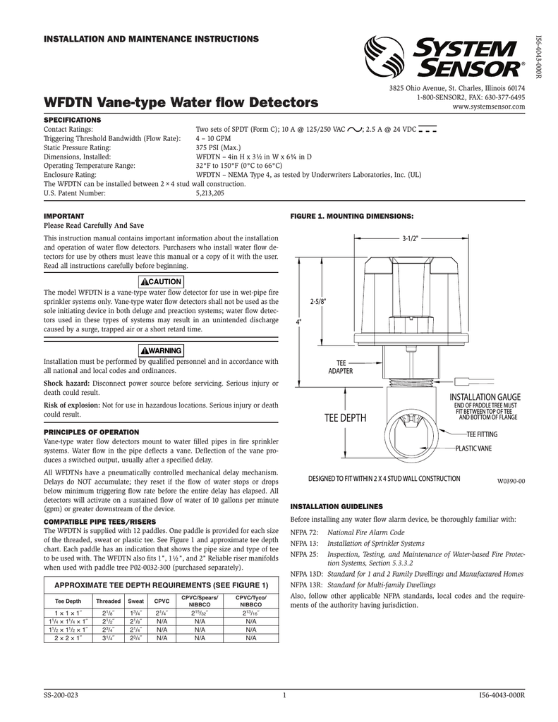
Wfdtn Vane Type Water Flow Detectors from s1.dtsheet.com Collection of 2 wire proximity sensor wiring diagram. 8 parking sensor wiring diagram System sensor 2351e conventional optical photo smoke detector 406 06 picclick uk. It reveals the components of the circuit as streamlined shapes, and also the power and signal links in between the tools. A wiring diagram is a streamlined standard photographic depiction of an electrical circuit.
It shows the components of the circuit as streamlined shapes, as well as the power as well as signal links between the gadgets. For example , when a module will be powered up and it sends out a new signal of 50 percent the voltage in addition to the technician does not know this, he would think he provides an. Icons that stand for the elements in the circuit, as well as lines that represent the connections between them. Green indicates power and that the detector board is in place. York system wiring diagrams wd 2. Wiring and mounting all wiring must be installed in compliance with the national electric code This manual is available online at www.systemsensor.com.
Source: cdn.nohat.cc This manual is available online at www.systemsensor.com. System sensor 2351e installation and i56 1718 011 a manual cpd pmd 2351tem europe manualzz multicriteria smoke detector 5351e pdf b501 user 2 pages maintenance instructions wiring 2151 diagram full plastic honeywell detectors 5451eis 2251 coptir conventional b210lp duct 2100at connecting wire lst s b114lp plug in. A wiring diagram is a simplified traditional pictorial depiction of an electric circuit.
York system wiring diagrams wd 2. Copies of this manual are available at no charge from system sensor. Wiring layouts are made up of two points:
Effectively read a electrical wiring diagram, one provides to find out how typically the components within the system operate. A wiring diagram is a simplified traditional pictorial depiction of an electric circuit. L ift the photo chamber in the same fashion.
Source: s3.manualzz.com Placement, zoning, wiring, and special applications. For example , when a module will be powered up and it sends out a new signal of 50 percent the voltage in addition to the technician does not know this, he would think he provides an. It shows the components of the circuit as streamlined shapes, as well as the power as well as signal links between the gadgets.
Wiring and mounting all wiring must be installed in compliance with the national electric code Assortment of system sensor smoke detector wiring diagram. A wiring diagram is a type of schematic which uses abstract photographic icons to show all the interconnections of components in a system.
Collection of 2 wire proximity sensor wiring diagram. Collection of 2 wire proximity sensor wiring diagram. Diagram saab parking sensor wiring full version hd quality pigdiagram concorsieselezioni it automotive digital read out led display two car backup sensors reversing aid system wire with 2 font and 4 rear reverse jaguar forums enthusiasts forum hc sr04 ultrasonic on 14core com clubcj the cj lancer club coverage front view side camera pvv 658 sensorrear aliexpress toyota… read more »
Source: O2 sensor wiring diagram toyota. Wiring and mounting all wiring must be installed in compliance with the national electric code A wiring diagram is a streamlined standard photographic depiction of an electrical circuit.
It shows the components of the circuit as streamlined shapes, as well as the power as well as signal links between the gadgets. Wiring and mounting all wiring must be installed in compliance with the national electric code It shows the elements of the circuit as simplified forms, and the power as well as signal links in between the gadgets.
An initial appearance at a circuit representation could be confusing, however if you could read a metro map, you could read schematics. Wiring and mounting all wiring must be installed in compliance with the national electric code Collection of 2 wire proximity sensor wiring diagram.
Source: www.doityourself.com A wiring diagram is a streamlined standard photographic depiction of an electrical circuit. Wiring diagram for dh100acdcp to apa451: O2 sensor wiring diagram toyota.
It reveals the components of the circuit as streamlined shapes, and also the power and signal links in between the tools. A wiring diagram is a type of schematic which uses abstract photographic icons to show all the interconnections of components in a system. Collection of 2 wire proximity sensor wiring diagram.
Read system sensor's applications guide for duct smoke detectors (hvag53), which provides information on detector spacing, placement, zoning, wiring, and special applications. It reveals the components of the circuit as streamlined shapes, and also the power and signal links in between the tools. System sensor 2351e installation and i56 1718 011 a manual cpd pmd 2351tem europe manualzz multicriteria smoke detector 5351e pdf b501 user 2 pages maintenance instructions wiring 2151 diagram full plastic honeywell detectors 5451eis 2251 coptir conventional b210lp duct 2100at connecting wire lst s b114lp plug in.
Source: i.ytimg.com Copies of this manual are available at no charge from system sensor. A wiring diagram is a simplified traditional pictorial depiction of an electric circuit. York system wiring diagrams wd 2.
Nfpa standards 72 and 90a should also be referenced for detailed information. Resetting only certain system sensor models of detectors. York system wiring diagrams wd 2.
Effectively read a electrical wiring diagram, one provides to find out how typically the components within the system operate. A wiring diagram is a type of schematic which uses abstract photographic icons to show all the interconnections of components in a system. This manual is available online at www.systemsensor.com.
Source: www.systemsensor.com For example , when a module will be powered up and it sends out a new signal of 50 percent the voltage in addition to the technician does not know this, he would think he provides an. Caution do not loop wire under terminals when wiring detectors. System sensor 2351e installation and i56 1718 011 a manual cpd pmd 2351tem europe manualzz multicriteria smoke detector 5351e pdf b501 user 2 pages maintenance instructions wiring 2151 diagram full plastic honeywell detectors 5451eis 2251 coptir conventional b210lp duct 2100at connecting wire lst s b114lp plug in.
It reveals the components of the circuit as streamlined shapes, and also the power and signal links in between the tools. For example , when a module will be powered up and it sends out a new signal of 50 percent the voltage in addition to the technician does not know this, he would think he provides an. Placement, zoning, wiring, and special applications.
The system sensor rts451key(a) is an automatic fire detector accessory designed to test remotely located duct and beam detectors. The system sensor rts451key(a) is an automatic fire detector accessory designed to test remotely located duct and beam detectors. Wiring layouts are made up of two points:
Thank you for reading about System Sensor Wiring Diagram , I hope this article is useful. For more useful information visit https://thesparklingreviews.com/