Home
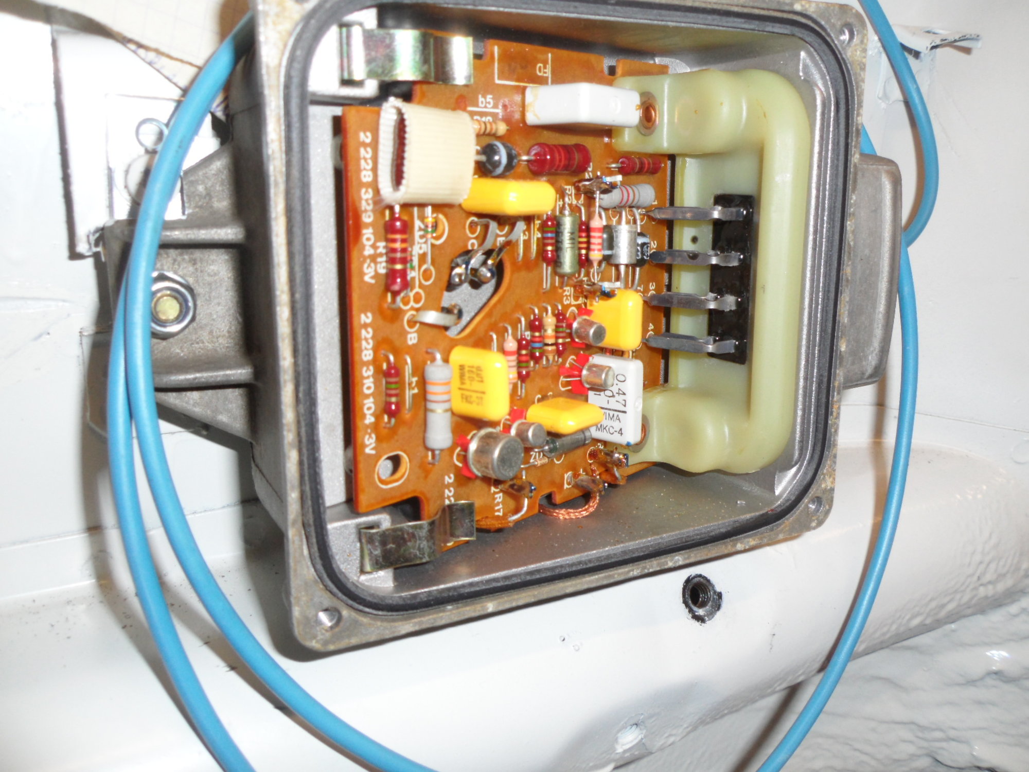
Bosch Ignition Module Wiring Diagram . Standard ignition tune up and then remove the mechanical advance unit. See the owner's manual, shop manual, or clymers, haynes or chitech manuals for
Ignition Module Bosch 0 227 100 008 Wiring Rennlist Porsche Discussion Forums from cimg7.ibsrv.net Not all manuals will have this information. Diagram together with gm hei ignition module wiring diagram on gm. The ignition control module has two connectors. 28, 2007 — electrical circuit diagrams Locate the ignition module positive (+) wire.
• when you are looking at a wiring diagram on a 2013 or newer vehicle, click on a connector number 1995 6 5 glow plug relay issues diesel bombers. Some of these conditions are dangerous. Megasquirt 2 issue fixed third generation f body message. 636 159 69 3 193 aveo engine diagram wiring resources. Ccf61 gm ignition module wiring diagram digital resources. There should be a reading of battery voltage at the wire.
Source: i.ibb.co Wire seouence has been arranged 70 simplify schematic. 636 159 69 3 193 aveo engine diagram wiring resources. Cucv wiring schematic wiring diagram centre.
Tape off the other end. Use shielded/grounded cable that is supplied for wiring crankshaft and camshaft signals. Not all manuals will have this information.
As you might guess, the placement can change based on the type of vehicle, so it is important to have the correct diagram or you will be practically going in blind. Gm hei module wiring diagram wiring schematic diagram. 6 5l turbo diesel lift pump relay harness.
Source: sw-em.com To locate the ignition module, refer to a wiring diagram for your vehicle's particular make and model. Splice the light green wire in plug #1 above in to this red/light green wire. Keep sensor wiring away from high voltage or noisy/dirty components and wiring, especially secondary ignition wiring, ignition boxes and associated wiring.
The typical elements in a wiring diagram are ground, power supply, cable and also link, output tools, switches, resistors, logic gate, lights, and so on. Looking down at the ignition module (with the ignition module still bolted in place), you'll notice that the ignition control module has a left connector and a right connector. Not all manuals will have this information.
Image result for gm ignition module testing ignite ignition. Result 90 percent of battery voltage or greater less than 90 percent of battery voltage diagnosis and testing (continued) 3 test step module voltage. 6 6 duramax wiring schematic wiring diagram.
Source: cimg5.ibsrv.net Learn to navigate this systems wiring circuitry and diagram using current flow analysis relay and module operation and neutral switch actuation such as circuit completion. Here is a basic wiring diagram that applies to all vintage and antique lawn and garden tractors using a stator charging system and a. 1995 6 5 glow plug relay issues diesel bombers.
Properly solder and heat shrink any wire connections. As you might guess, the placement can change based on the type of vehicle, so it is important to have the correct diagram or you will be practically going in blind. Use a wiring diagram for the year model of your vehicle.
Ccf61 gm ignition module wiring diagram digital resources. Basic ignition system wiring diagram. To read a wiring diagram, initially you need to know what basic components are included in a wiring diagram, and also which pictorial symbols are utilized to represent them.
Source: Find the red/light green wire in the gray rectangle plug (#3) above. Splice the light green wire in plug #1 above in to this red/light green wire. The typical elements in a wiring diagram are ground, power supply, cable and also link, output tools, switches, resistors, logic gate, lights, and so on.
Diagram together with gm hei ignition module wiring diagram on gm. Worn or damaged ignition switch, tgnttlon module note. Diagram 6 5 diesel glow plug wiring diagram 1993 dodge.
Soon after durant was forced out of gm's, he began to cooperate. 3200, 4100, 4200, 4300, 4400, 7300, 7400, 7500, 7600, 7700, 8500, 8600, mxt, rxt models built oct. Standard ignition tune up and then remove the mechanical advance unit.
Source: www.ccee.nl Worn or damaged ignition switch, tgnttlon module note. To read a wiring diagram, initially you need to know what basic components are included in a wiring diagram, and also which pictorial symbols are utilized to represent them. Diagram together with gm hei ignition module wiring diagram on gm.
Use shielded/grounded cable that is supplied for wiring crankshaft and camshaft signals. Gas cook top igniter diagnosis: Use a wiring diagram for the year model of your vehicle.
Some of these conditions are dangerous. Ccf61 gm ignition module wiring diagram digital resources. Worn or damaged ignition switch, tgnttlon module note.
Source: rollaclub.nyc3.digitaloceanspaces.com Properly solder and heat shrink any wire connections. Properly solder and heat shrink any wire connections. The typical elements in a wiring diagram are ground, power supply, cable and also link, output tools, switches, resistors, logic gate, lights, and so on.
Cucv wiring schematic wiring diagram centre. Diagram together with gm hei ignition module wiring diagram on gm. Image result for gm ignition module testing ignite ignition.
The typical elements in a wiring diagram are ground, power supply, cable and also link, output tools, switches, resistors, logic gate, lights, and so on. Diagram 6 5 diesel glow plug wiring diagram 1993 dodge. Module for bosch and distributors.
Thank you for reading about Bosch Ignition Module Wiring Diagram , I hope this article is useful. For more useful information visit https://thesparklingreviews.com/
